Locator:
It is very important to understand the meaning of location before understanding abut the jigs and fixtures. The location refers to the establishment of a desired relationship between the workpiece and the jigs or fixture correctness of location directly influences the accuracy of the finished product. The jigs and fixtures are desired so that all undesirable movements of the workpiece can be restricted. Determination of the locating points and clamping of the workpiece serve to restrict movements of the component in any direction, while setting it in a particular pre-decided position relative to the jig. Before deciding the locating points it is advisable to find out the all possible degrees of freedom of the workpiece. Then some of the degrees of freedom or all of them are restrained by making suitable arrangements. These arrangements are called locators.
Principles of Locations:
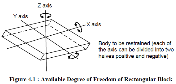
The principle of location is being discussed here with the help of a most popular example which is available in any of the book covering jigs and fixtures. It is important that one should understand the problem first.Any rectangular body many have three axis along x-axis, y-axis and z-axis. It can more along any of these axes or any of its movement can be released to these three axes. At the same time the body can also rotate about these axes too. So total degree of freedom of the body along which it can move is six. For processing the body it is required to restrain all the degree of freedom (DOF) by arranging suitable locating points and then clamping it in a fixed and required position. The basic principle used to locate the points is desirable below.
Six Points Location of a Rectangular Block:
Considering the six degree of freedom of a rectangular block as shown in Figure 4.1. It is made to rest on several points on the jig body. Provide a rest to workpiece on three points on the bottom x-y surface. This will stop the movement along z-axis, rotation with respect to x-axis and y-axis. Supporting it on the three points is considered as better support then one point or two points. Rest the workpiece on two points of side surface (x-z), this will fix the movement of workpiece along y-axis and rotation with respect to z-axis. Provide a support at one point of the adjacent surface (y-z) that will fix other remaining free movements. This principle of location of fixing points on the workpiece is also named as 3-2-1 principle of fixture design as number of points selected at different faces of the workpiece are 3, 2 and 1 respectively.
 Location of a Cylinder on a Vee Block:
The analysis of the principle of location of a cylinder on a Vee block is indicated in Figure 4.2. All the degrees of freedom of the cylindrical object are restrained. It is only fixed to move along axis AB. It can rotate about the axis AB. These free movements are also indicated in the figure. If the operation to be done on the cylindrical object requires restriction of the above mentioned free movements also than some more locating provisions must also be incorporated in addition to use of the Vee block.
 Different Methods for Used for Locating:
There are different methods used for location of a work. The locating arrangement should be decided after studying the type of work, type of operation, degree of accuracy required. Volume of mass production to be done also mattes a lot. Different locating methods are described below.
Flat Locator:
Flat locators are used for location of flat machined surfaces of the component. Three different examples which can be served as a general principle of location are described here for flat locators. These examples are illustrated in Figure 4.3.

A flat surface locator can be used as shown in first figure. In this case an undercut is provided at the bottom where two perpendicular surfaces intersect each other. This is made for swarf clearance. The middle figure shows flat headed button type locator. There is no need to made undercut for swarf clearance. The button can be adjusted to decide very fine location of the workpiece. There can be a vertical button support as shown in third figure, which is a better arrangement due to its capacity to bear end load and there is a provision for swarf clearance automatically.
Cylindrical Locator:
A cylindrical locator is shown in Figure 4.4. It is used for locating components having drilled holes. The cylindrical component to be located is gripped by a cylindrical locator fitted to the jig‟s body and inserted in the drilled hole of the component. The face of the jig‟s body around the locator is undercut to provide space for swarf clearance.

Conical Locator:
A conical locator is illustrated in Figure 4.5. This is used for locating the workpieces having cylindrical hole in the workpiece. The workpiece is found located by supporting it over the conical locator inserted into the drilled hole of the workpiece. A conical locator is considered as superior as it has a capacity to accommodate a slight variation in the hole diameter of the component without affecting the accuracy of location. Degree of freedom along z-axis can also be restrained by putting a template over the workpiece with the help of screws.

Jack Plane Locator:
Jack pin locator is used for supporting rough workpieces from the button as shown in Figure 4.6. Height of the jack pin is adjustable to accommodate the workpieces having variation in their surface texture. So this is a suitable method to accommodate the components which are rough and un-machined.

Drill Bush Locator:
The drill bush locator is illustrated in Figure 4.7. It is used for holding and locating the cylindrical workpieces. The bush has conical opening for locating purpose and it is sometimes screwed on the jig‟s body for the adjustment of height of the work.

Vee Locator:
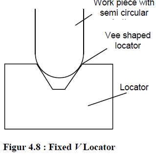
This is quick and effective method of locating the workpiece with desired level of accuracy. This is used for locating the circular and semi-circular type of workpieces as shown in Figure 4.8. The main part of locating device is Vee shaped block which is normally fixed to the jig. This locator can be of two types fixed Vee locator and adjustable Vee locator. The fixed type locator is normally fixed on the jig and
adjustable locator can be moved axially to provide proper grip of Vee band to the workpiece.
Published by Ravindra.K(Mechanical Engineering)
It is very important to understand the meaning of location before understanding abut the jigs and fixtures. The location refers to the establishment of a desired relationship between the workpiece and the jigs or fixture correctness of location directly influences the accuracy of the finished product. The jigs and fixtures are desired so that all undesirable movements of the workpiece can be restricted. Determination of the locating points and clamping of the workpiece serve to restrict movements of the component in any direction, while setting it in a particular pre-decided position relative to the jig. Before deciding the locating points it is advisable to find out the all possible degrees of freedom of the workpiece. Then some of the degrees of freedom or all of them are restrained by making suitable arrangements. These arrangements are called locators.
Principles of Locations:
The principle of location is being discussed here with the help of a most popular example which is available in any of the book covering jigs and fixtures. It is important that one should understand the problem first.Any rectangular body many have three axis along x-axis, y-axis and z-axis. It can more along any of these axes or any of its movement can be released to these three axes. At the same time the body can also rotate about these axes too. So total degree of freedom of the body along which it can move is six. For processing the body it is required to restrain all the degree of freedom (DOF) by arranging suitable locating points and then clamping it in a fixed and required position. The basic principle used to locate the points is desirable below.
Six Points Location of a Rectangular Block:
Considering the six degree of freedom of a rectangular block as shown in Figure 4.1. It is made to rest on several points on the jig body. Provide a rest to workpiece on three points on the bottom x-y surface. This will stop the movement along z-axis, rotation with respect to x-axis and y-axis. Supporting it on the three points is considered as better support then one point or two points. Rest the workpiece on two points of side surface (x-z), this will fix the movement of workpiece along y-axis and rotation with respect to z-axis. Provide a support at one point of the adjacent surface (y-z) that will fix other remaining free movements. This principle of location of fixing points on the workpiece is also named as 3-2-1 principle of fixture design as number of points selected at different faces of the workpiece are 3, 2 and 1 respectively.
The analysis of the principle of location of a cylinder on a Vee block is indicated in Figure 4.2. All the degrees of freedom of the cylindrical object are restrained. It is only fixed to move along axis AB. It can rotate about the axis AB. These free movements are also indicated in the figure. If the operation to be done on the cylindrical object requires restriction of the above mentioned free movements also than some more locating provisions must also be incorporated in addition to use of the Vee block.

There are different methods used for location of a work. The locating arrangement should be decided after studying the type of work, type of operation, degree of accuracy required. Volume of mass production to be done also mattes a lot. Different locating methods are described below.
Flat Locator:
Flat locators are used for location of flat machined surfaces of the component. Three different examples which can be served as a general principle of location are described here for flat locators. These examples are illustrated in Figure 4.3.

A flat surface locator can be used as shown in first figure. In this case an undercut is provided at the bottom where two perpendicular surfaces intersect each other. This is made for swarf clearance. The middle figure shows flat headed button type locator. There is no need to made undercut for swarf clearance. The button can be adjusted to decide very fine location of the workpiece. There can be a vertical button support as shown in third figure, which is a better arrangement due to its capacity to bear end load and there is a provision for swarf clearance automatically.
Cylindrical Locator:
A cylindrical locator is shown in Figure 4.4. It is used for locating components having drilled holes. The cylindrical component to be located is gripped by a cylindrical locator fitted to the jig‟s body and inserted in the drilled hole of the component. The face of the jig‟s body around the locator is undercut to provide space for swarf clearance.

Conical Locator:
A conical locator is illustrated in Figure 4.5. This is used for locating the workpieces having cylindrical hole in the workpiece. The workpiece is found located by supporting it over the conical locator inserted into the drilled hole of the workpiece. A conical locator is considered as superior as it has a capacity to accommodate a slight variation in the hole diameter of the component without affecting the accuracy of location. Degree of freedom along z-axis can also be restrained by putting a template over the workpiece with the help of screws.

Jack Plane Locator:
Jack pin locator is used for supporting rough workpieces from the button as shown in Figure 4.6. Height of the jack pin is adjustable to accommodate the workpieces having variation in their surface texture. So this is a suitable method to accommodate the components which are rough and un-machined.

Drill Bush Locator:
The drill bush locator is illustrated in Figure 4.7. It is used for holding and locating the cylindrical workpieces. The bush has conical opening for locating purpose and it is sometimes screwed on the jig‟s body for the adjustment of height of the work.

Vee Locator:
This is quick and effective method of locating the workpiece with desired level of accuracy. This is used for locating the circular and semi-circular type of workpieces as shown in Figure 4.8. The main part of locating device is Vee shaped block which is normally fixed to the jig. This locator can be of two types fixed Vee locator and adjustable Vee locator. The fixed type locator is normally fixed on the jig and
adjustable locator can be moved axially to provide proper grip of Vee band to the workpiece.
Published by Ravindra.K(Mechanical Engineering)
No comments:
Post a Comment
Thank Q Your Feedback is Valuable........