Metal Forming & Powder Metallurgy
Fundamentals of Metal Forming:
There are four basic production processes for producing desired shape of a product. These are casting, machining, joining (welding, mechanical fastners, epoxy, etc.), and deformation processes. Casting process exploit the fluidity of a metal in liquid state as it takes shape and solidifies in a mold. Machining processes provide desired shape with good accuracy and precision but tend to waste material in the generation of removed portions. Joining processes permit complex shapes to be constructed from simpler components and have a wide domain of applications.
Deformation processes exploit a remarkable property of metals, which is their ability to flow plastically in the solid state without deterioration of their properties. With the application of suitable pressures, the material is moved to obtain the desired shape with almost no wastage. The required pressures are generally high and the tools and equipment needed are quite expensive. Large production quantities are often necessary to justify the process.
To understand the forming of metal, it is important to know the structure of metals. Metals are crystalline in nature and consist of irregularly shaped grains of various sizes. Each grain is made up of atoms in an orderly arrangement, known as a lattice. The orientation of the atoms in a grain is uniform but differs in adjacent grains. When a force is applied to deform it or change its shape, a lot of changes occur in the grain structure. These include grain fragmentation, movement of atoms, and lattice distortion. Slip planes develop through the lattice structure at points where the atom bonds of attraction are the weakest and whole blocks of atoms are displaced. The orientation of atoms, however, does not change when slip occurs.
To deform the metal permanently, the stress must exceed the elastic limit. At room temperature, the metal is in a more rigid state than when at higher temperature. Thus, to deform the metal greater pressures are needed when it is in cold state than when in hot state.
When metal is formed in cold state, there is no recrystallization of grains and thus recovery from grain distortion or fragmentation does not take place. As grain deformation proceeds, greater resistance to this action results in increased hardness and strength. The metal is said to be strain hardened. There are several theories to explain this occurrence. In general, these refer to resistance build up in the grains by atomic dislocation, fragmentation, or lattice distortion, or a combination of the three phenomena.
The amount of deformation that a metal can undergo at room temperature depends on its ductility. The higher the ductility of a metal, the more the deformation it can undergo. Pure metals can withstand greater amount of deformation than metals having alloying elements, since alloying increases the tendency and rapidity of strain hardening. Metals having large grains are more ductile than those having smaller grains.
When metal is deformed in cold state, severe stresses known as residual stresses are set up in the material. These stresses are often undesirable, and to remove them the metal is heated to some temperature below the recrystalline range temperature. In this temperature range, the stresses are rendered ineffective without appreciable change in physical properties or grain structure.
COLD AND HOT WORKING OF METALS:
Cold Working:
Plastic deformation of metals below the recrystallization temperature is known as cold working. It is generally performed at room temperature. In some cases, slightly elevated temperatures may be used to provide increased ductility and reduced strength. Cold working offers a number of distinct advantages, and for this reason various cold-working processes have become extremely important. Significant advances in recent years have extended the use of cold forming, and the trend appears likely to continue.
In comparison with hot working, the advantages of cold working are
1. No heating is required
2. Bettter surface finish is obtained
3. Better dimensional control is achieved; therefore no secondary machining is generally needed.
4. Products possess better reproducibility and interchangeablity.
5. Better strength, fatigue, and wear properties of material.
6. Directional properties can be imparted.
7. Contamination problems are almost negligible.
Some disadvantages associated with cold-working processes are:
1. Higher forces are required for deformation.
2. Heavier and more powerful equipment is required.
3. Less ductility is available.
4. Metal surfaces must be clean and scale-free.
5. Strain hardening occurs ( may require intermediate annealing ).
6. Undesirable residual stresses may be produced
Cold forming processes, in general, are better suited to large-scale production of parts because of the cost of the required equipment and tooling.
Warm Working:
Metal deformation carried out at temperatures intermediate to hot and cold forming is called Warm Forming . Compared to cold forming, warm forming offers several advantages. These include:
• Lesser loads on tooling and equipment
• Greater metal ductility
• Fewer number of annealing operation ( because of less strain hardening )
Compared to hot forming, warm forming offers the following advantages.
• Lesser amount of heat energy requirement
• Better precision of components
• Lesser scaling on parts
• Lesser decarburization of parts
• Better dimensional control
• Better surface finish
• Lesser thermal shock on tooling
• Lesser thermal fatigue to tooling, and so greater life of tooling.
Hot Working:
Plastic deformation of metal carried out at temperature above the recrystallization temperature, is called hot working. Under the action of heat and force, when the atoms of metal reach a certain higher energy level, the new crystals start forming. This is called recrystallization. When this happens, the old grain structure deformed by previously carried out mechanical working no longer exist, instead new crystals which are strain-free are formed.
In hot working, the temperature at which the working is completed is critical since any extra heat left in the material after working will promote grain growth, leading to poor mechanical properties of material.
In comparison with cold working, the advantages of hot working are
*No strain hardening
*Lesser forces are required for deformation
*Greater ductility of material is available, and therefore more deformation is possible.
*Favorable grain size is obtained leading to better mechanical properties of material
*Equipment of lesser power is needed
*No residual stresses in the material.
Some disadvantages associated in the hot-working of metals are:
*Heat energy is needed
*Poor surface finish of material due to scaling of surface
*Poor accuracy and dimensional control of parts
*Poor reproducibility and interchangeability of parts
*Handling and maintaining of hot metal is difficult and troublesome
*Lower life of tooling and equipment.
FORGING:
Forging is a process in which material is shaped by the application of localized compressive forces exerted manually or with power hammers, presses or special forging machines. The process may be carried out on materials in either hot or cold state. When forging is done cold, processes are given special names. Therefore, the term forging usually implies hot forging carried out at temperatures which are above the recrystallization temperature of the material.
Forging is an effective method of producing many useful shapes. The process is generally used to produce discrete parts. Typical forged parts include rivets, bolts, crane hooks, connecting rods, gears, turbine shafts, hand tools, railroads, and a variety of structural components used to manufacture machinery. The forged parts have good strength and toughness; they can be used reliably for highly stressed and critical applications.
A variety of forging processes have been developed that can be used for either producing a single piece or mass – produce hundreds of identical parts. Some common forging processes are:
*Open – die hammer forging
*Impression – die drop forging
*Press Forging
*Upset Forging
*Swaging
*Rotary Forging
*Roll forging
Open – Die Hummer Forging:
It is the simplest forging process which is quite flexible but not suitable for large scale production. It is a slow process. The resulting size and shape of the forging are dependent on the skill of the operator.

Open die forging does not confine the flow of metal, Fig 2.1. The operator obtains the desired shape of forging by manipulating the work material between blows. Use may be made of some specially shaped tools or a simple shaped die between the work piece and the hammer or anvil to assist in shaping the required sections (round, concave, or convex), making holes, or performing cut – off operations. This process is most often used to make near – final shape of the part so that some further operation done on the job produces the final shape.
Forging Force. In open die forging operation, the forging force F, to be applied on a solid cylindrical component can be determined from the relation.

Where s f is the flow stress of the material, µ is the coefficient of friction, and d and h are the diameter and height of the work piece, respectively.
Impression – Die Drop Forging (Closed – Die Forging):
The process uses shaped dies to control the flow of metal. The heated metal is positioned in the lower cavity and on it one or more blows are struck by the upper die. This hammering makes the metal to flow and fill the die cavity completely. Excess metal is squeezed out around the periphery of the cavity to form flash. On completion of forging, the flash is trimmed off with the help of a trimming die.
Most impression – die sets contain several cavities. The work material is given final desired shape in stages as it is deformed in successive cavities in the die set. The shape of the cavities cause the metal to flow in desired direction, thereby imparting desired fibre structure to the component.
Auto – Forging:
This is a modified form of impression – die forging, used mainly for non – ferrous metals.
In this a cast preform, as removed from the mold while hot, is finish – forged in a die. The flash formed during die forging is trimmed later in the usual manner. As the four steps of the process – casting, transfer from mold to the forging die, forging, and trimming are in most applications completely mechanized, the process has acquired the name Auto – forging.
Coining:
It is a closed – die forging process used mainly for minting coins and making of jewelry. In order to produce fine details on the work material the pressures required are as large as five or six times the strength of the material. Lubricants are not employed in this process because they can get entrapped in the die cavities and, being incompressible, prevent the full reproduction of fine details of the die.
Net - shape Forging (Precession Forging):
Modern trend in forging operation is toward economy and greater precision. The metal is deformed in cavity so that no flash is formed and the final dimensions are very close to the desired component dimensions. There is minimum wastage of material and need for subsequent machining operation is almost eliminated.
The process uses special dies having greater accuracies than those in impression – die gorging, and the equipment used is also of higher capacity. The forces required for forging are high. Aluminum and magnesium alloys are more suitable although steel can also be precision – forged. Typical precision – forged components are gears, turbine blades, fuel injection nozzles, and bearing casings.
Because of very high cost of toolings and machines, precision forging is preferred over conventional forging only where volume of production is extremely large.
Forging Force Requirement:
The forging force, F, required to forge material by impression – die forging operation can be determined by the relation
F = k . s f . A
where k is a constant f is the flow stress of material at the forging temperature, and A is the projected area of the forging including the flash.
In hot forging of most non – ferrous metals and alloys, the forging pressure is generally in the range of 500 MPa to 1000 MPa.
Press Forging:
Press forging, which is mostly used for forging of large sections of metal, uses hydraulic press to obtain slow and squeezing action instead of a series of blows as in drop forging. The continuous action of the hydraulic press helps to obtain uniform deformation throughout the entire depth of the workpiece. Therefore, the impressions obtained in press forging are more clean.
Press forgings generally need smaller draft than drop forgings and have greater dimensional accuracy. Dies are generally heated during press forging to reduce heat loss, promote more uniform metal flow and production of finer details.
Hydraulic presses are available in the capacity range of 5 MN to 500 MN but 10 MN to 100MN capacity presses are more common.
Upset Forging:
Upset forging involves increasing the cross – section of a material at the expense of its corresponding length. Upset – forging was initially developed for making bolt heads in a continuous manner, but presently it is the most widely used of all forging processes. Parts can be upset – forged from bars or rods upto 200 mm in diameter in both hot and cold condition. Examples of upset forged parts are fasteners, valves, nails, and couplings.
The process uses split dies with one or several cavities in the die. Upon separation of split die, the heated bar is moved from one cavity to the next. The split dies are then forced together to grip the and a heading tool (or ram) advances axially against the bar, upsetting it to completely fill the die cavity. Upon completion of upsetting process the heading tool comes back and the movable split die releases the stock.
Upsetting machines, called upsetters, are generally horizontal acting.
When designing parts for upset – forging, the following three rules must be followed.
The length of unsupported bar that can be upset in one blow of heading tool should not exceed 3 times the diameter of bar. Otherwise bucking will occur.
For upsetting length of stock greater than 3 times the diameter the cavity diameter must not exceed 1.5 times the dia of bar.
For upsetting length of stock greater than 3 times the diameter and when the diameter of the upset is less than 1.5 times the diameter of the bar, the length of un – supported stock beyond the face of die must not exceed diameter of the stock.
Roll Forging:
This process is used to reduce the thickness of round or flat bar with the corresponding increase in length. Examples of products produced by this process include leaf springs, axles, and levers.
The process is carried out on a rolling mill that has two semi – cylindrical rolls that are slightly eccentric to the axis of rotation. Each roll has a series of shaped grooves on it. When the rolls are in open position, the heated bar stock is placed between the rolls. With the rotation of rolls through half a revolution, the bar is progressively squeezed and shaped. The bar is then inserted between the next set of smaller grooves and the process is repeated till the desired shape and size are achieved.
 Swaging:
In this process, the diameter of a rod or a tube is reduced by forcing it into a confining die. A set of reciprocation dies provides radial blows to cause the metal to flow inward and acquire the form of the die cavity. The die movements may be of in – and – out type or rotary. The latter type is obtained with the help of a set of rollers in a cage, in a similar action as in a roller bearing. The workpiece is held stationary and the dies rotate, the dies strike the workpiece at a rate as high as 10 - 20 strokes per second.
Screwdriver blades and soldering iron tips are typical examples of swaged products and other products made by swaging.
 The process is quite versatile. The maximum diameter of work piece that can be swaged is limited to about 150 mm; work pieces as small as 0.5 mm diameter have been swaged. The production rate can be as high as 30 parts per minute depending upon the complexity of the part shape and the part handling means adopted.
The parts produced by swaging have tolerance in the range ± 0.05 mm to ± 0.5 mm and improved mechanical properties. Use of lubricants helps in obtaining better work surface finish and longer die life. Materials, such as tungsten and molybdenum are generally swaged at elevated temperatures as they have low ductility at room temperature. Hot swaging is also used to form long or steep tapers, and for large reductions.
Swaging is a noisy operation. The level of noise can be, however, reduced by proper mounting of the machine or by the use of enclosure.
WIRE DRAWING:
Wire drawing is primarily the same as bar drawing except that it involves smaller – diameter material that can be coiled. It is generally performed as a continuous operation on draw bench like the one shown in Fig.
Large coil of hot rolled material of nearly 10 mm diameter is taken and subjected to preparation treatment before the actual drawing process. The preparation treatment for steel wire consists of :
*Cleaning. This may be done by acid pickling, rinsing, and drying. Or, it may be done by mechanical flexing.
*Neutralization. Any remaining acid on the raw material is neutralized by immersing it in a lime bath. The corrosion protected material is also given a thin layer of lubricant.
 To begin the drawing process, one end of coil is reduced in cross section upto some length and fed through the drawing die, and gripped. A wire drawing die is generally made of tungsten carbide and has the configuration.
Small diameter wire is generally drawn on tandom machines which consists of a series of dies, each held in a water – cooled die block. Each die reduces the cross section by a small amount so as to avoid excessive strain in the wire. Intermediate annealing of material between different states of wire may also be done, if required.
Die pull
The force required to pull the stock through the die (under frictionless conditions) can be computed as follows.
 Where F = die pull, i.e. the force required to pull the stock through the die
Yavg = average true stress of the material in the die gap
Ao , Af = original and final areas of cross section of material.
Alternatively, the following expression can be used
F = c st (Ao - Af )
where c is a constant whose value is in the range 1.5 to 3.0 depending upon the % area reduction, (lower value for higher % reduction), and st is tensile strength of material before drawing.
The pull force determines the machine capacity needed.
 TUBE DRAWING
The diameter and wall thickness of tubes that have been produced by extrusion or other processes can be reduced by tube drawing process. The process of tube drawing (Fig 3.5) is similar to wire or rod drawing except that it usually requires a mandrel of the requisite diameter to form the internal hole.
Tubes as large as 0.3 m in diameter can be drawn.
Drawing Equipment:
Drawing equipment can be of several designs. These designs can be classified into two basic types; Draw bench, and Bull block. A draw bench uses a single die and the pulling force is supplied by a chain drive or by hydraulic means. Draw bench is used for single length drawing of rod or tube with diameter greater than 20mm. Length can be as much as 30 m. The drawing speed attainable on a draw bench ranges from 5 m/min to 50 m/min. Draw benches are available having capacities to provide pull force of upto 1 MN.
 FORMABILITY OF SHEET METAL:
Formability may be defined as the ease with which material may be forced into a permanent change of shape.
The formability of a material depends on several factors. The important one concerns the properties of material like yield strength, strain hardening rate, and ductility. These are greatly temperature - dependent. As the temperature of material is increased, the yield strength and rate of strain hardening progressively reduce and ductility increases. The hot working of metal, therefore, permits relatively very large amount of deformation before cracking.
There are several methods of predicting formability. A brief description of some important methods follows.
A drawing ratio of 50 % is considered excellent. As shown in Fig 4.1(a), either a flat bottom punch with lubricated blank may be used to draw the cup, or as shown in Fig 4.1(b) a blank may be drawn by a lubricated hemi – spherical punch. In the first case, the action is principally that of drawing in which cylindrical stretching of material takes place. In the second case, there will be bi – axial stretching of the material. For drawing, the clamping force is just sufficient to prevent buckling of the material at the draw radius as it enters the die. The deformation takes place in the flange and over the draw radius.
Fukui Conical – Cup Test:
It utilizes a hemispherical, smoothly polished punch. No blank holder is required. In each test, a drawing ratio which will result in a broken cup is determined. Formation of wrinkles is avoided by using a fixed ratio between the thickness of the sheet, the size of the blank, and the punch and die diameters. Under these conditions, the test produces a known amount of stretching, drawing, and bending under tension.
Normal Anisotropy Coefficient:
The material is subjected to uni-axial tensile test. The anisotropy coefficient is derived from the ratio of the plastic width strain eW to the thickness strain et . A material with a high plastic anisotropy also has a greater “thinning resistance.” In general, the higher the anisotropy coefficient the better the material deforms in drawing operations.
Strain-Hardening Coefficient:
Strain hardening refers to the fact that as a metal deforms in some area, dislocations occur in the microstructure. As these dislocations pile up, they tend to strengthen the metal against further deformation in that area. Thus the strain is spread throughout the sheet. However, at some point in the deformations, the strain suddenly localizes and necking, or localized thinning, develops. When this occurs, little further overall deformation of the sheet can be obtained without it fracturing in the necked region.
The strain – hardening coefficient therefore reflects how well the metal distributes the strain throughout the sheet, avoiding or delaying localized necking. The higher the strain – hardening coefficient, the move the material will harden as it is being stretched and the greater will be the resistance to localized necking. Necks in the metal harm surface appearance and affect structural integrity.
For many stamping operations, stretching of the metal is the critical factor and is dependent on the strain – hardening coefficient. Therefore, stampings that need much drawing should be made from metal having high average strain – hardening coefficients. Yield strength should be low to avoid wrinkles or buckling.
Forming Limit Curve:
The forming – limit curve is a good index of determining the formability of sheet metal. Essentially, it requires to draw a curve that shows a boundary line between acceptable strain levels in forming and those that may cause failure.
The curve indicates the relation between major and minor strains that are perpendicular to the plane of the sheet. To determine these strains, a grid of circles is marked on the sheet metal, say by an electrolytic stencil – etching process. After the metal is deformed, the circles are measured to obtain the major strain e1 and the minor strain e2.Typically, ten to fifteen data points are obtained from a test specimen in the region of fracture. Ellipses lying both in the failed region and just outside of it are measured. The forming – limit curve is then drawn to fall below the strains in the necked and fractured zones, and above the strains found just outside these zones.
With controlled variation in specimen size it is possible to plot an entire forming – limit curve from one test setup. A reasonably accurate forming limit curve may be obtained with four specimens while a precision curve may be obtained with eight specimens.
In may be noted that “local” ductility varies for different metals, so no universal forming – limit curve can be developed. For example, two metals may have peak local ductilities of 20% and 50% at a given minor strain. The metal with the 20 % local ductility (high strain – hardening coefficient) may turn out to be the best choice because the strain will then have a better distribution throughout, allowing the entire sheet to be stretched 20%. If the other sheet showed little strain hardening, it might stretch by 50% in local area, but leave the rest of the sheet relatively unstrained.
Through the use of formability – prediction techniques. Designers and fabricators are able to make a wiser choice of metals and obtain date quickly on newer metals. The essential data can be obtained before the die is designed. Also metal suppliers will be able to establish whether a material possesses required formability before it is shipped from the plant.
SHEARING:
Shearing is a cutting operation used to remove a blank of required dimensions from a large sheet. To understand the shearing mechanism, consider a metal being sheared between a punch and a die, Typical features of the sheet and the slug are also shown in this figure. As can be seen that cut edges are neither smooth nor perpendicular to the plane of the sheet.
Shearing starts as the punch presses against the sheet metal. At first, cracks form in the sheet on both the top and bottom edges (marked T and T', in the figure). As the punch descends further, these cracks grow and eventually meet each other and the slug separates from the sheet. A close look at the fractured surfaces will revel that these are quite rough and shiny; rough because of the cracks formed earlier, and shiny because of the contact and rubbing of the sheared edge against the walls of the die.
The clearance between the punch and the die plays an important role in the determination of the shape and quality of the sheared ege. There is an optimum range for the clearance, which is 2 to 10% of the sheet thickness, for the best results. If the clearance increases beyond this, the material tends to be pulled into the die and the edges of the sheared zone become rougher. The ratio of the shining (burnished) area to the rough area on the sheared edge decreases with increasing clearance and sheet thickness. The quality of sheared edge is also affected by punch speed; greater the punch speed better the edge quality.
Shearing Operations:
For general purpose shearing work, straight line shears are used.
Shearing may also be done between a punch and die.The shearing operations make which use of a die, include punching, blanking, piercing, notching, trimming, and nibbling.
Piercing:
It is a process by which a hole is cut (or torn) in metal. It is different from punching in that piercing does not generate a slug. Instead, the metal is pushed back to form a jagged flange on the back side of the hole.
A pierced hole looks somewhat like a bullet hole in a sheet of metal.
Trimming:
When parts are produced by die casting or drop forging, a small amount of extra metal gets spread out at the parting plane. This extra metal, called flash, is cut – off before the part is used, by an operation called trimming. The operation is very similar to blanking and the dies used are also similar to blanking dies. The presses used for trimming have, however, relatively larger table.
Notching:
It is an operation in which a specified small amount of metal is cut from a blank. It is different from punching in the sense that in notching cutting line of the slug formed must touch one edge of the blank or strip. A notch can be made in any shape. The purpose of notching is generally to release metal for fitting up.
Nibbling:
Nibbling is variation of notching, with overlapping notches being cut into the metal. The operation may be resorted to produce any desired shape, for example flanges, collars, etc.
Perforating:
Perforating is an operation is which a number of uniformly spaced holes are punched in a sheet of metal. The holes may be of any size or shape. They usually cover the entire sheet of metal.
 Published by Ravindra,Mechanical
Fundamentals of Metal Forming:
 |
| State of the stresses metal undergo during deformation. |
Deformation processes exploit a remarkable property of metals, which is their ability to flow plastically in the solid state without deterioration of their properties. With the application of suitable pressures, the material is moved to obtain the desired shape with almost no wastage. The required pressures are generally high and the tools and equipment needed are quite expensive. Large production quantities are often necessary to justify the process.
To understand the forming of metal, it is important to know the structure of metals. Metals are crystalline in nature and consist of irregularly shaped grains of various sizes. Each grain is made up of atoms in an orderly arrangement, known as a lattice. The orientation of the atoms in a grain is uniform but differs in adjacent grains. When a force is applied to deform it or change its shape, a lot of changes occur in the grain structure. These include grain fragmentation, movement of atoms, and lattice distortion. Slip planes develop through the lattice structure at points where the atom bonds of attraction are the weakest and whole blocks of atoms are displaced. The orientation of atoms, however, does not change when slip occurs.
To deform the metal permanently, the stress must exceed the elastic limit. At room temperature, the metal is in a more rigid state than when at higher temperature. Thus, to deform the metal greater pressures are needed when it is in cold state than when in hot state.
When metal is formed in cold state, there is no recrystallization of grains and thus recovery from grain distortion or fragmentation does not take place. As grain deformation proceeds, greater resistance to this action results in increased hardness and strength. The metal is said to be strain hardened. There are several theories to explain this occurrence. In general, these refer to resistance build up in the grains by atomic dislocation, fragmentation, or lattice distortion, or a combination of the three phenomena.
The amount of deformation that a metal can undergo at room temperature depends on its ductility. The higher the ductility of a metal, the more the deformation it can undergo. Pure metals can withstand greater amount of deformation than metals having alloying elements, since alloying increases the tendency and rapidity of strain hardening. Metals having large grains are more ductile than those having smaller grains.
When metal is deformed in cold state, severe stresses known as residual stresses are set up in the material. These stresses are often undesirable, and to remove them the metal is heated to some temperature below the recrystalline range temperature. In this temperature range, the stresses are rendered ineffective without appreciable change in physical properties or grain structure.
COLD AND HOT WORKING OF METALS:
Cold Working:
Plastic deformation of metals below the recrystallization temperature is known as cold working. It is generally performed at room temperature. In some cases, slightly elevated temperatures may be used to provide increased ductility and reduced strength. Cold working offers a number of distinct advantages, and for this reason various cold-working processes have become extremely important. Significant advances in recent years have extended the use of cold forming, and the trend appears likely to continue.
In comparison with hot working, the advantages of cold working are
1. No heating is required
2. Bettter surface finish is obtained
3. Better dimensional control is achieved; therefore no secondary machining is generally needed.
4. Products possess better reproducibility and interchangeablity.
5. Better strength, fatigue, and wear properties of material.
6. Directional properties can be imparted.
7. Contamination problems are almost negligible.
Some disadvantages associated with cold-working processes are:
1. Higher forces are required for deformation.
2. Heavier and more powerful equipment is required.
3. Less ductility is available.
4. Metal surfaces must be clean and scale-free.
5. Strain hardening occurs ( may require intermediate annealing ).
6. Undesirable residual stresses may be produced
Cold forming processes, in general, are better suited to large-scale production of parts because of the cost of the required equipment and tooling.
Warm Working:
Metal deformation carried out at temperatures intermediate to hot and cold forming is called Warm Forming . Compared to cold forming, warm forming offers several advantages. These include:
• Lesser loads on tooling and equipment
• Greater metal ductility
• Fewer number of annealing operation ( because of less strain hardening )
Compared to hot forming, warm forming offers the following advantages.
• Lesser amount of heat energy requirement
• Better precision of components
• Lesser scaling on parts
• Lesser decarburization of parts
• Better dimensional control
• Better surface finish
• Lesser thermal shock on tooling
• Lesser thermal fatigue to tooling, and so greater life of tooling.
Hot Working:
Plastic deformation of metal carried out at temperature above the recrystallization temperature, is called hot working. Under the action of heat and force, when the atoms of metal reach a certain higher energy level, the new crystals start forming. This is called recrystallization. When this happens, the old grain structure deformed by previously carried out mechanical working no longer exist, instead new crystals which are strain-free are formed.
In hot working, the temperature at which the working is completed is critical since any extra heat left in the material after working will promote grain growth, leading to poor mechanical properties of material.
In comparison with cold working, the advantages of hot working are
*No strain hardening
*Lesser forces are required for deformation
*Greater ductility of material is available, and therefore more deformation is possible.
*Favorable grain size is obtained leading to better mechanical properties of material
*Equipment of lesser power is needed
*No residual stresses in the material.
Some disadvantages associated in the hot-working of metals are:
*Heat energy is needed
*Poor surface finish of material due to scaling of surface
*Poor accuracy and dimensional control of parts
*Poor reproducibility and interchangeability of parts
*Handling and maintaining of hot metal is difficult and troublesome
*Lower life of tooling and equipment.
FORGING:
Forging is a process in which material is shaped by the application of localized compressive forces exerted manually or with power hammers, presses or special forging machines. The process may be carried out on materials in either hot or cold state. When forging is done cold, processes are given special names. Therefore, the term forging usually implies hot forging carried out at temperatures which are above the recrystallization temperature of the material.
Forging is an effective method of producing many useful shapes. The process is generally used to produce discrete parts. Typical forged parts include rivets, bolts, crane hooks, connecting rods, gears, turbine shafts, hand tools, railroads, and a variety of structural components used to manufacture machinery. The forged parts have good strength and toughness; they can be used reliably for highly stressed and critical applications.
A variety of forging processes have been developed that can be used for either producing a single piece or mass – produce hundreds of identical parts. Some common forging processes are:
*Open – die hammer forging
*Impression – die drop forging
*Press Forging
*Upset Forging
*Swaging
*Rotary Forging
*Roll forging
Open – Die Hummer Forging:
It is the simplest forging process which is quite flexible but not suitable for large scale production. It is a slow process. The resulting size and shape of the forging are dependent on the skill of the operator.

Open die forging does not confine the flow of metal, Fig 2.1. The operator obtains the desired shape of forging by manipulating the work material between blows. Use may be made of some specially shaped tools or a simple shaped die between the work piece and the hammer or anvil to assist in shaping the required sections (round, concave, or convex), making holes, or performing cut – off operations. This process is most often used to make near – final shape of the part so that some further operation done on the job produces the final shape.
Forging Force. In open die forging operation, the forging force F, to be applied on a solid cylindrical component can be determined from the relation.
Where s f is the flow stress of the material, µ is the coefficient of friction, and d and h are the diameter and height of the work piece, respectively.
Impression – Die Drop Forging (Closed – Die Forging):
The process uses shaped dies to control the flow of metal. The heated metal is positioned in the lower cavity and on it one or more blows are struck by the upper die. This hammering makes the metal to flow and fill the die cavity completely. Excess metal is squeezed out around the periphery of the cavity to form flash. On completion of forging, the flash is trimmed off with the help of a trimming die.
Most impression – die sets contain several cavities. The work material is given final desired shape in stages as it is deformed in successive cavities in the die set. The shape of the cavities cause the metal to flow in desired direction, thereby imparting desired fibre structure to the component.
Auto – Forging:
This is a modified form of impression – die forging, used mainly for non – ferrous metals.
In this a cast preform, as removed from the mold while hot, is finish – forged in a die. The flash formed during die forging is trimmed later in the usual manner. As the four steps of the process – casting, transfer from mold to the forging die, forging, and trimming are in most applications completely mechanized, the process has acquired the name Auto – forging.
Coining:
It is a closed – die forging process used mainly for minting coins and making of jewelry. In order to produce fine details on the work material the pressures required are as large as five or six times the strength of the material. Lubricants are not employed in this process because they can get entrapped in the die cavities and, being incompressible, prevent the full reproduction of fine details of the die.
Net - shape Forging (Precession Forging):
Modern trend in forging operation is toward economy and greater precision. The metal is deformed in cavity so that no flash is formed and the final dimensions are very close to the desired component dimensions. There is minimum wastage of material and need for subsequent machining operation is almost eliminated.
The process uses special dies having greater accuracies than those in impression – die gorging, and the equipment used is also of higher capacity. The forces required for forging are high. Aluminum and magnesium alloys are more suitable although steel can also be precision – forged. Typical precision – forged components are gears, turbine blades, fuel injection nozzles, and bearing casings.
Because of very high cost of toolings and machines, precision forging is preferred over conventional forging only where volume of production is extremely large.
Forging Force Requirement:
The forging force, F, required to forge material by impression – die forging operation can be determined by the relation
F = k . s f . A
where k is a constant f is the flow stress of material at the forging temperature, and A is the projected area of the forging including the flash.
In hot forging of most non – ferrous metals and alloys, the forging pressure is generally in the range of 500 MPa to 1000 MPa.
Press Forging:
Press forging, which is mostly used for forging of large sections of metal, uses hydraulic press to obtain slow and squeezing action instead of a series of blows as in drop forging. The continuous action of the hydraulic press helps to obtain uniform deformation throughout the entire depth of the workpiece. Therefore, the impressions obtained in press forging are more clean.
Press forgings generally need smaller draft than drop forgings and have greater dimensional accuracy. Dies are generally heated during press forging to reduce heat loss, promote more uniform metal flow and production of finer details.
Hydraulic presses are available in the capacity range of 5 MN to 500 MN but 10 MN to 100MN capacity presses are more common.
Upset Forging:
Upset forging involves increasing the cross – section of a material at the expense of its corresponding length. Upset – forging was initially developed for making bolt heads in a continuous manner, but presently it is the most widely used of all forging processes. Parts can be upset – forged from bars or rods upto 200 mm in diameter in both hot and cold condition. Examples of upset forged parts are fasteners, valves, nails, and couplings.
The process uses split dies with one or several cavities in the die. Upon separation of split die, the heated bar is moved from one cavity to the next. The split dies are then forced together to grip the and a heading tool (or ram) advances axially against the bar, upsetting it to completely fill the die cavity. Upon completion of upsetting process the heading tool comes back and the movable split die releases the stock.
Upsetting machines, called upsetters, are generally horizontal acting.
When designing parts for upset – forging, the following three rules must be followed.
The length of unsupported bar that can be upset in one blow of heading tool should not exceed 3 times the diameter of bar. Otherwise bucking will occur.
For upsetting length of stock greater than 3 times the diameter the cavity diameter must not exceed 1.5 times the dia of bar.
For upsetting length of stock greater than 3 times the diameter and when the diameter of the upset is less than 1.5 times the diameter of the bar, the length of un – supported stock beyond the face of die must not exceed diameter of the stock.
Roll Forging:
This process is used to reduce the thickness of round or flat bar with the corresponding increase in length. Examples of products produced by this process include leaf springs, axles, and levers.
The process is carried out on a rolling mill that has two semi – cylindrical rolls that are slightly eccentric to the axis of rotation. Each roll has a series of shaped grooves on it. When the rolls are in open position, the heated bar stock is placed between the rolls. With the rotation of rolls through half a revolution, the bar is progressively squeezed and shaped. The bar is then inserted between the next set of smaller grooves and the process is repeated till the desired shape and size are achieved.

In this process, the diameter of a rod or a tube is reduced by forcing it into a confining die. A set of reciprocation dies provides radial blows to cause the metal to flow inward and acquire the form of the die cavity. The die movements may be of in – and – out type or rotary. The latter type is obtained with the help of a set of rollers in a cage, in a similar action as in a roller bearing. The workpiece is held stationary and the dies rotate, the dies strike the workpiece at a rate as high as 10 - 20 strokes per second.
Screwdriver blades and soldering iron tips are typical examples of swaged products and other products made by swaging.

The parts produced by swaging have tolerance in the range ± 0.05 mm to ± 0.5 mm and improved mechanical properties. Use of lubricants helps in obtaining better work surface finish and longer die life. Materials, such as tungsten and molybdenum are generally swaged at elevated temperatures as they have low ductility at room temperature. Hot swaging is also used to form long or steep tapers, and for large reductions.
Swaging is a noisy operation. The level of noise can be, however, reduced by proper mounting of the machine or by the use of enclosure.
WIRE DRAWING:
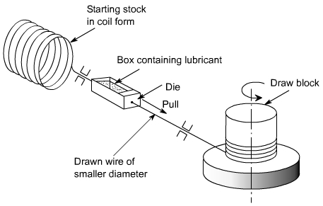 |
| Wire drawing on a continuous draw block. The rotating draw block provides a continuous pull on the incoming wire. |
Large coil of hot rolled material of nearly 10 mm diameter is taken and subjected to preparation treatment before the actual drawing process. The preparation treatment for steel wire consists of :
*Cleaning. This may be done by acid pickling, rinsing, and drying. Or, it may be done by mechanical flexing.
*Neutralization. Any remaining acid on the raw material is neutralized by immersing it in a lime bath. The corrosion protected material is also given a thin layer of lubricant.

Small diameter wire is generally drawn on tandom machines which consists of a series of dies, each held in a water – cooled die block. Each die reduces the cross section by a small amount so as to avoid excessive strain in the wire. Intermediate annealing of material between different states of wire may also be done, if required.
Die pull
The force required to pull the stock through the die (under frictionless conditions) can be computed as follows.
Yavg = average true stress of the material in the die gap
Ao , Af = original and final areas of cross section of material.
Alternatively, the following expression can be used
F = c st (Ao - Af )
where c is a constant whose value is in the range 1.5 to 3.0 depending upon the % area reduction, (lower value for higher % reduction), and st is tensile strength of material before drawing.
The pull force determines the machine capacity needed.
The diameter and wall thickness of tubes that have been produced by extrusion or other processes can be reduced by tube drawing process. The process of tube drawing (Fig 3.5) is similar to wire or rod drawing except that it usually requires a mandrel of the requisite diameter to form the internal hole.
Tubes as large as 0.3 m in diameter can be drawn.
Drawing Equipment:
Drawing equipment can be of several designs. These designs can be classified into two basic types; Draw bench, and Bull block. A draw bench uses a single die and the pulling force is supplied by a chain drive or by hydraulic means. Draw bench is used for single length drawing of rod or tube with diameter greater than 20mm. Length can be as much as 30 m. The drawing speed attainable on a draw bench ranges from 5 m/min to 50 m/min. Draw benches are available having capacities to provide pull force of upto 1 MN.
 FORMABILITY OF SHEET METAL:
Formability may be defined as the ease with which material may be forced into a permanent change of shape.
The formability of a material depends on several factors. The important one concerns the properties of material like yield strength, strain hardening rate, and ductility. These are greatly temperature - dependent. As the temperature of material is increased, the yield strength and rate of strain hardening progressively reduce and ductility increases. The hot working of metal, therefore, permits relatively very large amount of deformation before cracking.
There are several methods of predicting formability. A brief description of some important methods follows.
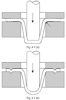
A drawing ratio of 50 % is considered excellent. As shown in Fig 4.1(a), either a flat bottom punch with lubricated blank may be used to draw the cup, or as shown in Fig 4.1(b) a blank may be drawn by a lubricated hemi – spherical punch. In the first case, the action is principally that of drawing in which cylindrical stretching of material takes place. In the second case, there will be bi – axial stretching of the material. For drawing, the clamping force is just sufficient to prevent buckling of the material at the draw radius as it enters the die. The deformation takes place in the flange and over the draw radius.
Fukui Conical – Cup Test:
It utilizes a hemispherical, smoothly polished punch. No blank holder is required. In each test, a drawing ratio which will result in a broken cup is determined. Formation of wrinkles is avoided by using a fixed ratio between the thickness of the sheet, the size of the blank, and the punch and die diameters. Under these conditions, the test produces a known amount of stretching, drawing, and bending under tension.
Normal Anisotropy Coefficient:
The material is subjected to uni-axial tensile test. The anisotropy coefficient is derived from the ratio of the plastic width strain eW to the thickness strain et . A material with a high plastic anisotropy also has a greater “thinning resistance.” In general, the higher the anisotropy coefficient the better the material deforms in drawing operations.
Strain-Hardening Coefficient:
Strain hardening refers to the fact that as a metal deforms in some area, dislocations occur in the microstructure. As these dislocations pile up, they tend to strengthen the metal against further deformation in that area. Thus the strain is spread throughout the sheet. However, at some point in the deformations, the strain suddenly localizes and necking, or localized thinning, develops. When this occurs, little further overall deformation of the sheet can be obtained without it fracturing in the necked region.
The strain – hardening coefficient therefore reflects how well the metal distributes the strain throughout the sheet, avoiding or delaying localized necking. The higher the strain – hardening coefficient, the move the material will harden as it is being stretched and the greater will be the resistance to localized necking. Necks in the metal harm surface appearance and affect structural integrity.
For many stamping operations, stretching of the metal is the critical factor and is dependent on the strain – hardening coefficient. Therefore, stampings that need much drawing should be made from metal having high average strain – hardening coefficients. Yield strength should be low to avoid wrinkles or buckling.
Forming Limit Curve:
The forming – limit curve is a good index of determining the formability of sheet metal. Essentially, it requires to draw a curve that shows a boundary line between acceptable strain levels in forming and those that may cause failure.
The curve indicates the relation between major and minor strains that are perpendicular to the plane of the sheet. To determine these strains, a grid of circles is marked on the sheet metal, say by an electrolytic stencil – etching process. After the metal is deformed, the circles are measured to obtain the major strain e1 and the minor strain e2.Typically, ten to fifteen data points are obtained from a test specimen in the region of fracture. Ellipses lying both in the failed region and just outside of it are measured. The forming – limit curve is then drawn to fall below the strains in the necked and fractured zones, and above the strains found just outside these zones.
With controlled variation in specimen size it is possible to plot an entire forming – limit curve from one test setup. A reasonably accurate forming limit curve may be obtained with four specimens while a precision curve may be obtained with eight specimens.
In may be noted that “local” ductility varies for different metals, so no universal forming – limit curve can be developed. For example, two metals may have peak local ductilities of 20% and 50% at a given minor strain. The metal with the 20 % local ductility (high strain – hardening coefficient) may turn out to be the best choice because the strain will then have a better distribution throughout, allowing the entire sheet to be stretched 20%. If the other sheet showed little strain hardening, it might stretch by 50% in local area, but leave the rest of the sheet relatively unstrained.
Through the use of formability – prediction techniques. Designers and fabricators are able to make a wiser choice of metals and obtain date quickly on newer metals. The essential data can be obtained before the die is designed. Also metal suppliers will be able to establish whether a material possesses required formability before it is shipped from the plant.
SHEARING:
Shearing is a cutting operation used to remove a blank of required dimensions from a large sheet. To understand the shearing mechanism, consider a metal being sheared between a punch and a die, Typical features of the sheet and the slug are also shown in this figure. As can be seen that cut edges are neither smooth nor perpendicular to the plane of the sheet.
Shearing starts as the punch presses against the sheet metal. At first, cracks form in the sheet on both the top and bottom edges (marked T and T', in the figure). As the punch descends further, these cracks grow and eventually meet each other and the slug separates from the sheet. A close look at the fractured surfaces will revel that these are quite rough and shiny; rough because of the cracks formed earlier, and shiny because of the contact and rubbing of the sheared edge against the walls of the die.
The clearance between the punch and the die plays an important role in the determination of the shape and quality of the sheared ege. There is an optimum range for the clearance, which is 2 to 10% of the sheet thickness, for the best results. If the clearance increases beyond this, the material tends to be pulled into the die and the edges of the sheared zone become rougher. The ratio of the shining (burnished) area to the rough area on the sheared edge decreases with increasing clearance and sheet thickness. The quality of sheared edge is also affected by punch speed; greater the punch speed better the edge quality.
Shearing Operations:
For general purpose shearing work, straight line shears are used.
Shearing may also be done between a punch and die.The shearing operations make which use of a die, include punching, blanking, piercing, notching, trimming, and nibbling.
Piercing:
It is a process by which a hole is cut (or torn) in metal. It is different from punching in that piercing does not generate a slug. Instead, the metal is pushed back to form a jagged flange on the back side of the hole.
A pierced hole looks somewhat like a bullet hole in a sheet of metal.
Trimming:
When parts are produced by die casting or drop forging, a small amount of extra metal gets spread out at the parting plane. This extra metal, called flash, is cut – off before the part is used, by an operation called trimming. The operation is very similar to blanking and the dies used are also similar to blanking dies. The presses used for trimming have, however, relatively larger table.
Notching:
It is an operation in which a specified small amount of metal is cut from a blank. It is different from punching in the sense that in notching cutting line of the slug formed must touch one edge of the blank or strip. A notch can be made in any shape. The purpose of notching is generally to release metal for fitting up.
Nibbling:
Nibbling is variation of notching, with overlapping notches being cut into the metal. The operation may be resorted to produce any desired shape, for example flanges, collars, etc.
Perforating:
Perforating is an operation is which a number of uniformly spaced holes are punched in a sheet of metal. The holes may be of any size or shape. They usually cover the entire sheet of metal.
Published by Ravindra,Mechanical
Very finished article! I hope you'll post more of other good stuffs. Thank you!
ReplyDelete